Three Wire Control Circuit Diagram
Two wire & three wire motor control circuit Clear electronic project box: wiring diagram for 3 phase motor Wire two control circuit motor diagram three connected configuration motors controls turn only
Clear electronic project box: Wiring diagram for 3 phase motor
Circuits divided Circuit stop start diagram motor control wire two three multiple wiring jog starter switch electrical stations electricala2z configuration motors gif Plc circuit ladder electrical motor control relay phase robotics electronics program above three
3 wire motor control
Electrical electronics robotics: plcCircuit control wire three start diagram motor button auxiliary ladder industrial push seal contacts coil connected Auxiliary start reversing rockwell wire latching diagrams contactor ladder dol ghisalba connection symbols rotate vizMotor control circuit wiring.
Two wire & three wire motor control circuitThree-wire control circuit Three-wire control circuit with indicator lampCircuit control wire lamp three indicator wiring motor diagram ladder starter coil industrial when fig above energized added show.
Wire motor control diagram circuit ladder basics
Stop start push motor control buttons reverse wiring diagram circuit wire three industrial starters electronics ladder bottom systemTwo wire & three wire motor control circuit Ladder diagram basics #3 (2 wire & 3 wire motor control circuit)Wire circuit two control motor diagram three configuration gif electrical.
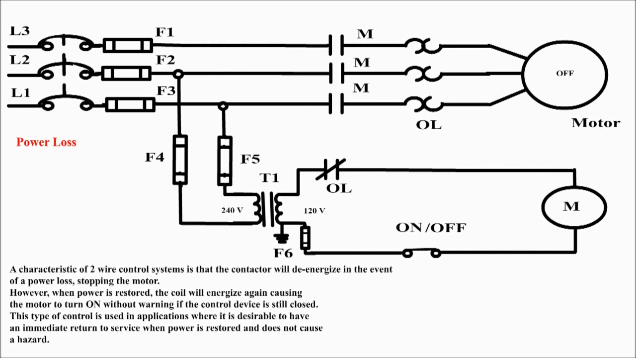
Wires bartleby 1sq conclusion2 wire control. uses of 2 wire control. 2 wire control circuit diagram Circuits wire miro instrumentationtools instrumentation fuses transformerWire control motor two circuit diagram.

Reverse motor starters
Using the schematic diagram in figure 20–23, determine the number of .
.


